|
| |
 |
The gumbootwireless.net No. 8 Wire, 19Dbi Parabolic Dish These instructions are preliminary. If anything is unclear or you have any questions please contact us and we will update this page. This project just uses solder to attach the wires. If you have gas, mig/tig or a spot welder you should obviously use that instead. The pictures show plans that are a bit different to those available here. They were an earlier version I was working on. Materials and tools
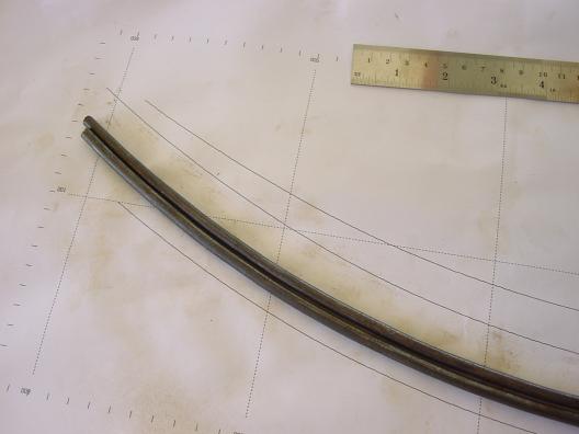
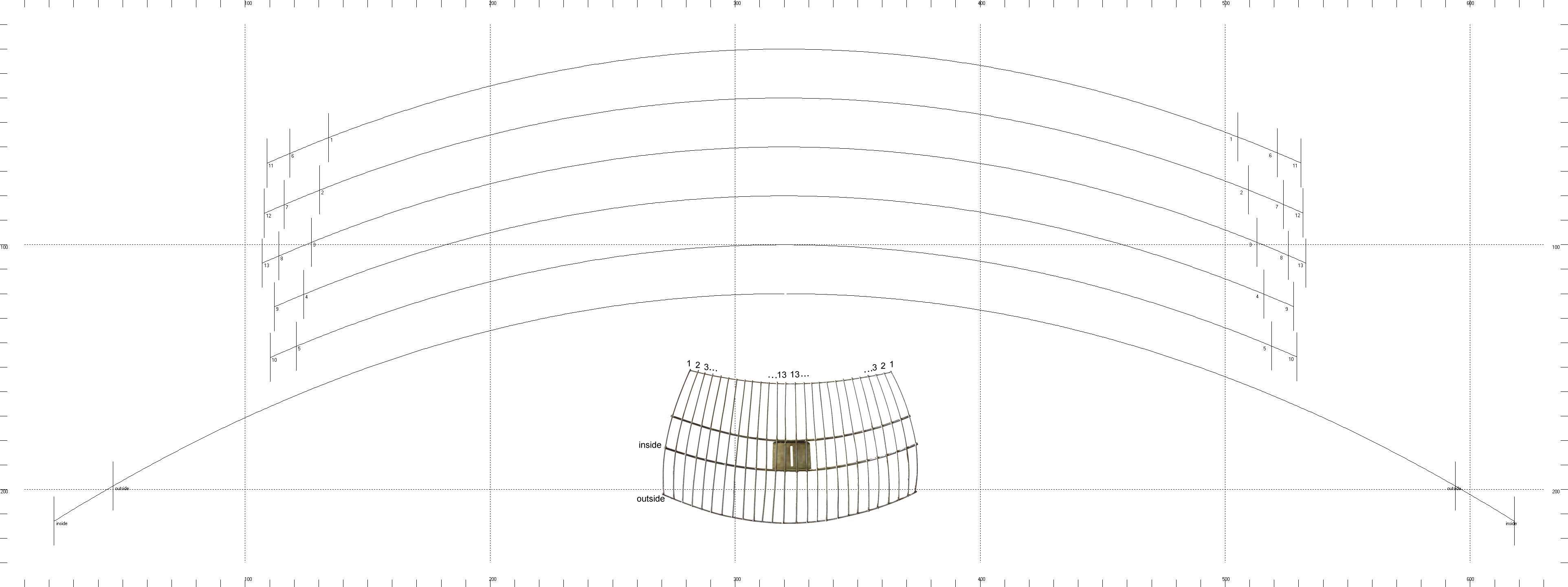
1) First save a copy of the plan. You need to print this out at true size which will require sticking several pages together with tape. There are graduations marked along the edge of the paper in centimetres to allow you to check the printout is scaled correctly. The entire image should be 64x24cm when printed out. Ensure your printout is no more than 1mm out either in width or height. The plan is used for a bending guide for the wires and rod. All the wires are the same shape but they are different lengths. Each wire is labelled with a number (1 to 13) or a name (inside, outside). The position of each of these wires in the final dish is indicated by the inset dish image. Note that the dish has 26 wires across but both sides are symetrical so only 13 different lengths are needed.
Start by bending the two 6mm rods to shape (indicated by the "inside" wire marking). This is easily bent over your knee if you
don't have a vice. If you don't have a vice the ends of the rod are hard to bend so just start in from the end 5 cm or so then trim
the unused part off afterwards with a hacksaw. Bend the rod only few degrees and move along the rod a few centimetres each time.
Sit the rod on top
of the plan between bends to see where it starts to deviate from the line and correct that bend before moving on. The lines indicate
the inside curve of the wire. You need to
work the bends backwards and forwards a bit as you move along the length of the rod to get it to match up well. All the bends in
this project must match up exactly along the entire length of steel. If you're not prepared to be patient getting the bends right
then this may not be a project for you.
Next bend the 2 number 1 wires and 2 number 8 wires. If you're using high-tensile wire it tends to bend back to the shape of
the roll it came from more easily than bending it straight. If using high-tensile it may be easier for you to bend the wire
slightly straighter than the required curve then work it back to the correct shape.
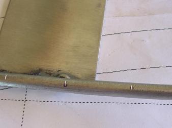
2) When I made this dish I welded a plate to the steel bars before I soldered the wires on. If you don't
have a welder but want a steel plate (useful for mounting the dish) you should solder the plate on after making the dish itself.
3)Mark the wire positions on the rods. Each wire should be 25mm apart on the rod (from center to center of
the wires). The frequency of 802.11b is 2.44Ghz which requires the gap between wires is no more than 24.4mm. The thickness of the
No.8 wire itself gives us a slight safety margin. Start marking from the outside ends of each rod working back towards the
center. Do 13 marks then repeat from the other end.
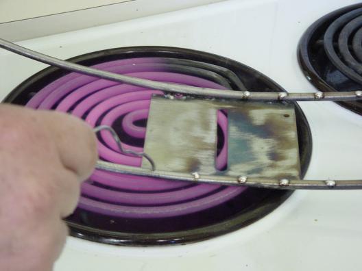
4)Tin all marked positions on the rods and wires. A stove element does the fastest job of tinning (don't blame me if you burn yourself because you weren't being careful). Note: Lead solder is toxic. There are alternatives becoming available but if you're still using lead solder like me then ensure you have good ventilation and avoid inhaling the fumes. Check with anyone else who uses the stove first and clean up well afterwards. If you're not happy using the stove take the hot plate off your bbq and use that or get a butane soldering iron as seen in the background of picture 2. Butane soldering irons are excellent for use in the feild and the tip can be screwed off to use the butane flame directly.
Make sure the
part you're tinning is good and hot before soldering it. Good tinning will make the solder appear to melt into the steel.
Bad tinnig will just look like a lump of solder sitting on top of the wire and it will easily break off. If in doubt go hotter
until you get a feel for good and bad tinning. If you're tinning galvanisd wire the solder will literally (and quite suddenly)
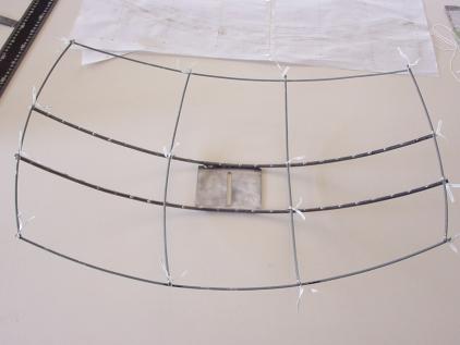
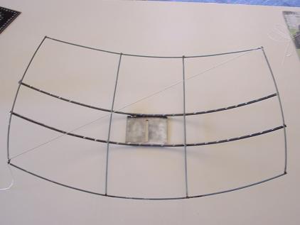
flow in and merge with the galvanising. 5) Loosely tie the dish together with twist ties using wires 1 and 8 as shown below. All the cross wires sit on top of the "inside" and "outside" rods/wires. The two "inside" rods should be 9.5cm apart (from center to center) and run parallel along the entire legth of the dish. The "outside" wires attach at the end of the numbered wires which sit just on top of the "outside" wires. Mark off the positions on the number 1 and 8 wires where they cross the "inside" wires (mark on the outer side of the curve), then remove them and tin the marks you made and tin the ends of the wires. It may be useful to score the ends of the wires 2 or 3mm from the end so the tinning doesn't stick right on the end of the wire. Take a look at the final image if you're unsure what the relative wire locations are.
6) Tie the dish back together with twist ties and start soldering the joins as shown below. Remove a twist tie,
hold the joint in place and press a hot soldering iron on the join until the two tinned sides melt together.
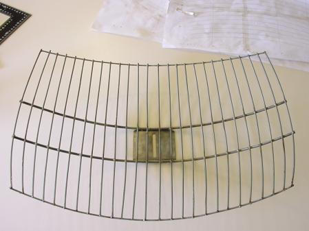
7) Now comes the tedious part. You need to bend the rest of the wires to shape and cut them to length.
Then put each wire in place on the dish and mark the positions where they cross the "inside" wires. Once they are all
marked, score the marks and tin them (including the ends of the wire) as before. After the wires are tinned solder them in place.
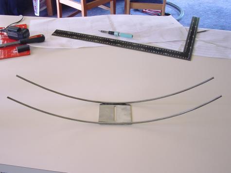
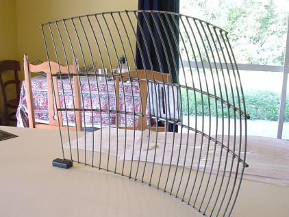
8) And you should end up with a dish that looks something like the one below. You can then solder on a plate if desired.
Remember to tin the edges of the plate before attaching it.
|
|
© 2004-2005, Sentient Research
|
|